In order to carry out this project we are using the Hexsoon EDU450 platform (quadcopter X). This drone frame is a relatively low cost frame including motors, ESCs and propellers, designed especially for developing and testing. To be able to flight the drone are necessary more things, for this reason each team received a kit with all the required equipment (including the frame). In the following table we explain a little bit each component and where is possible to purchase it and its cost.
This platform is very interesting because there is an specific parameter file to adjust correctly the drone, called hexsoon-edu450.param. This parameter file can also be loaded using the Mission Planner’s: Config/Tuning >> Full Parameter Tree page by selecting “hexsoon-edu450” from the drop down on the middle right and then push the “Load Presaved” button.
| COMPONENTS | BRIEF DESCRIPTION | PRICE (€) |
| HEXSOON EDU450 KIT | Drone frame, ESC’s (Electronic Speed Controller), motors, power distributor, propellers, screws, spacers and nuts. | 299.90 |
| PIXHAWK 2.1 STANDARD SET CUBE ORANGE | Flight controller with ADS-B (Automatic Dependent Surveillance-Broadcast) Uavionix receiver. It is included the power module, buzzer, adhesive foam and all the necessary cables. | 301.00 |
| GPS HERE 3 | GNSS (Global Navigation Satellite System) receiver with RTK (Real Time Kinematics), compass . Only available using the CAN (Controller Area Network) protocol. | 151.00 |
| TELEMETRY RADIO SET V3 433MHz | Open source radio platform that typically allows ranges of better than 300. The radio uses open source firmware which has been specially designed to work well with MAVLink packets and to be integrated with the Mission Planner, Copter, Rover and Plane. The radio used is 433MHz. | 54.95 |
| G.T.POWER BATTERY CHECKER | Digital battery capacity checker. We are using 4S Lithium Polymer batteries, so it is very important to check ofen the voltage of each cell battery. | 7.79 |
| RASPBERRY PI 4 MODEL B 8GB | On board computer to implement into the drone. With this device is possible to connect the flight controller and send orders from the computer to the desired payload implemented. | 98.99 |
| RASPBERRY PI CAMERA MODULE 2 | Raspberry Pi Camera Module 2 to be connected in the CSI-2 port. Resolution of 3280 x 2464 pixels and 30 photos per seconds | 23.57 |
| LIGHTWARE LW20/C | The LW20/C is a small form factor, 100 meter range, laser sensor in an IP67 enclosure suitable for small drones and self-driving vehicles, where weight, size and power consumption are critical. The LW20/C includes driver hardware and software to control a servo driven LiDAR scanner for sense-and-avoid applications | 241.51 |
| FRSKY TARANIS X9D PLUS SE | RC transmitter with 24 channels compatible with OpenTX. This device is used to control the drone manually with the joysticks and configure some functions with the different sticks. | 279.99 |
| HEXAGONAL SCREWDRIVERS PACK | Hexagonal screwdrivers pack RS PRO: 1.27mm, 1.5mm, 2mm, 2.5mm, 3mm, 3.5mm, 4mm, 4.5mm, 5mm, 5.5mm, 6mm, 7mm, 8mm. | 17.85 |
| INTERCHANGEABLE SCREWDRIVER PACK | Interchangeable screwdriver pack. Flat: 1.5mm, 2.0mm, 3.0mm, 4.0mm. Torx: T5, T6, T7, T8. Phillips: PH0, PH00, PH000. | 17.70 |
| FIXED KEYS SET | Set of fixed keys: 4mm, 4.5mm, 5mm, 5.5mm, 6.0mm, 7.0mm, 8.0mm, 9.0mm, 10.0mm, 11.0mm | 25.05 |
| DRONE PAD | Drone Take-off and landing pad foldable. | 11.67 |
| BATTERY | Litium Polymer battery Bashing. 5000mAh, 50C,4S1P. | 52.99 |
| 1566.11 |
After the description of the elements we will start with the assembly, which is divided in two parts: Assembly 1 and Assembly 2.
ASSEMBLY 1
In this first part we should mount all the drone frame, which includes the two carbon plates of the central body, the power distribution board, the four arms, ESCs and motors and finally the landing gear.
The first step is to assembly the power distribution board below the upper carbon plate, with the XT60 connector pointing backwards. Then we should fixed the motors on the bench, taking into account the rotation of each motor, according to Figure 1.
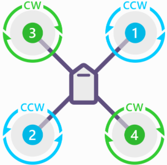
QUADCOPTER X
Figure 1: Quadcopter X. (Source: https://ardupilot.org/copter/docs/connect-escs-and-motors.html)
The following step is to connect the ESC with the motor, introducing it inside the arm and then fixing one of the end to the central body and the other with the bench motor and the landing gear. It is very important to fix the orange arms at the drone face in order to know the orientation when it is flying. Once the arms are fixed, is possible to connect the ESCs (+VCC and GND) with the power distribution board. There are two cables more (black and white) that should be connected to the flight controller, we will see this step in the Assembly 2.
The placement of the different sensors or elements is important. For example, when we bind the receiver we must press a small hole. It is important to have accessible the receiver so that you don’t have to mount and dismount each time the receiver from the platform. The battery is another element, because his weight it is important to have it properly centered, it can unbalance the drone once it starts to fly.It is also important to tighten with small cable ties all the elements that can be moved of loose.
Errors in this phase:
The main mistake made in this phase was placing the motors in the wrong turning order. How do we solve it? Reversing the polarity, changing wires.
Once assembled, it seemed that the drone was well adjusted, however, reviewing all the screws we realized that many were loose or had not been tightened well.
ASSEMBLY 2
Now is the time to assembly all the electronic devices in the drone. We have already connected the motors, ESC, and the power distribution board, so we must connect now the flight controller Pixhawk Orange Cube, the RC receiver, the GPS Here 3, the altimeter, the optical sensor, the Holybro telemetry radio and the buzzer.
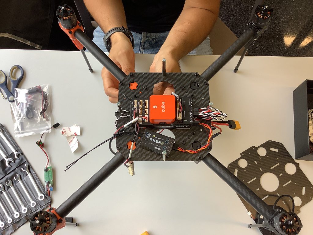
The flight controller should be installed in the middle of the central body and with the arrow pointing forwards. Once the flight controller is installed on the top center platform of the drone we should connect the different devices to it. The first device to connect is the SBUS OUT RC receiver to the RCIN in the autopilot. Then we connect the signal cables of the motors to the MAIN OUT ports 1, 2, 3 and 4 according to the number of the Figure 1. It is important to use a cable extension for the 1 and 3 motors.
Now, we mount the GPS on the transparent plate and we connect it to CAN 1 port. The following step is to fix the structure that contains the radio altimeter and the optical sensor and connect to CAN 2 and I2C 2 ports respectivelly. Finally we should connect the telemetry radio to TELEM 1 and the buzzer with the USB cable to the USB port. As a final step it is very important to fix all the components of the drone very well.
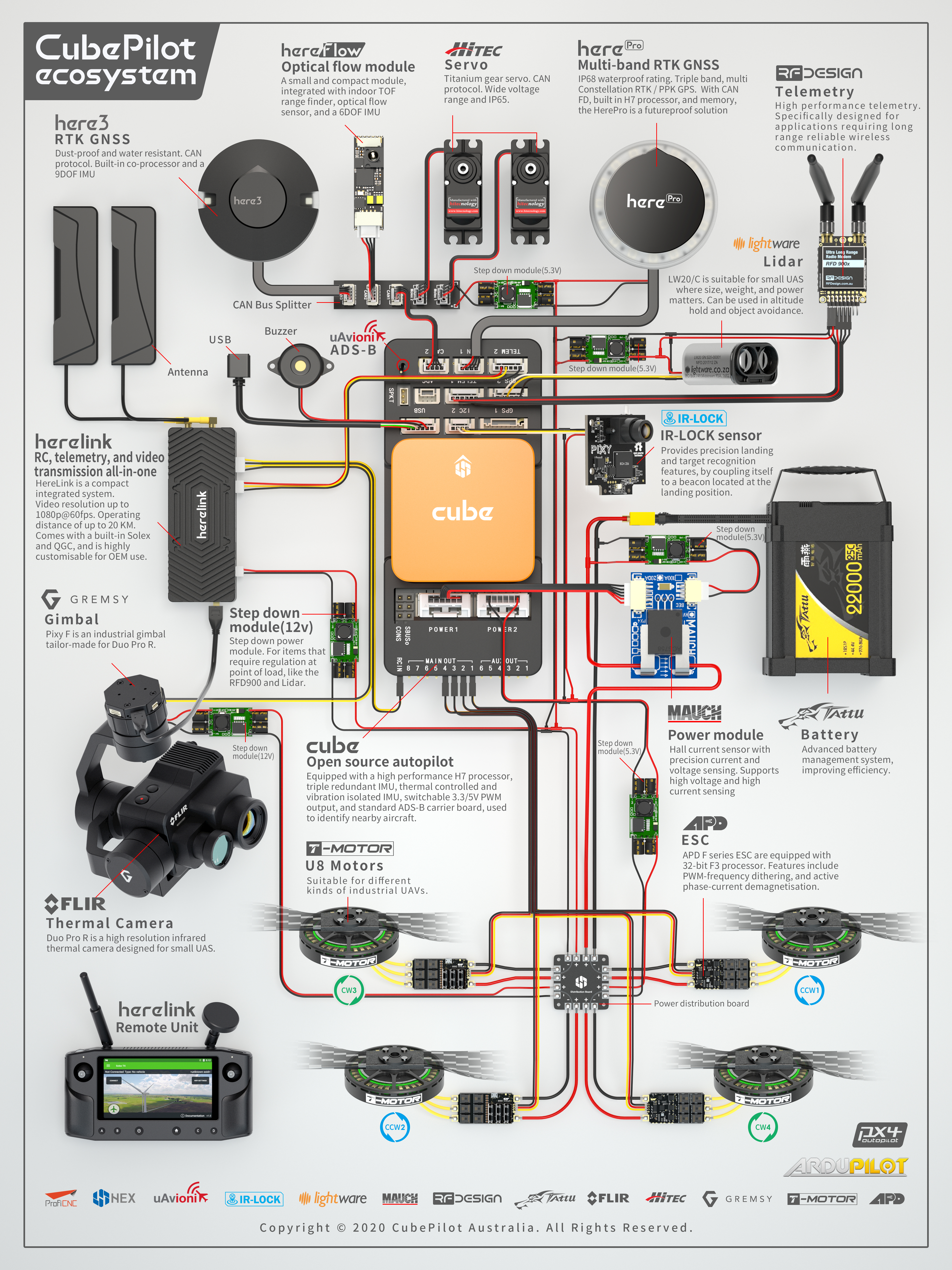
The following picture is a good scheme to follow in order to do the autopilot connections well.