Introduction
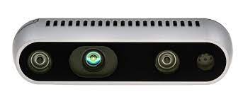
In this section we will talk about navigation systems based on optical technology as a source for positioning and navigation. This type of navigation is useful for those places where the satellite signal is not possible. In this work we will use two cameras, the Intel RealSense T256 and the Intel D435. Our group will use the D435, and as its name suggests, it uses RealSense technology. This tecnology uses three separate optical scanners, a 1080p high-definition optical camera, an infrared camera and an infrared laser projector, to read the environment around you. Working together, these three optical scanners can detect depth, detect human movement, and scan 3D objects with accuracy and precision. To meet diverse needs and use cases, this technology is further offered in two different applications: short-range and long-range.
RealSense Short Range Camera – The RealSense Short Range Camera is ideal for home and office applications. It detects hand gestures and facial features, and can scan objects close to the camera. The RealSense Short Range Camera is best suited for indoor use at close range, making it perfect for the individual user who wants to explore new ways to interact with their device.
RealSense Long Range Camera – While the RealSens Short Range Camera is designed for indoor use at close range, the RealSense Long Range Camera is ideal for outdoor and indoor use at greater distances
Protection against vibrations.

Best location of the camera and protection against brivations.

Objectives
1.Analysis of the location of the camera on the drone.
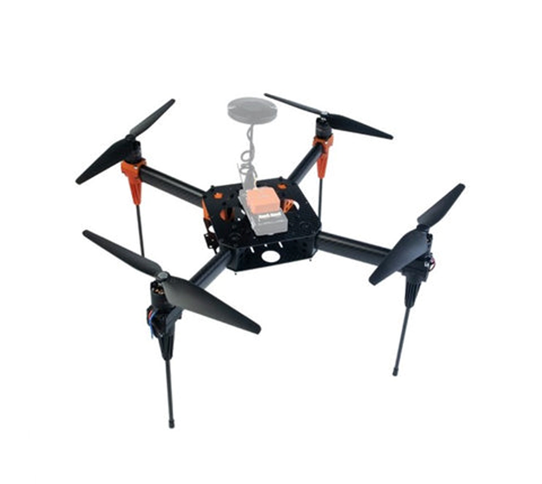
As we have previously mentioned, the model we use in our project is the Hexsoon EDU450, this model is a quadcopter drone. This drone has been assembled in our classrooms and there is a link on our blog where you can find the assembly description.
.https://med.upc.edu/team4-2021/assembly/
HEXSOON EDU450
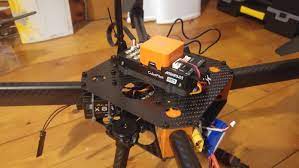
It is important to note that we will use the camera for indoor navigation (distance detection) traking the objects and the depth of the frame (x,y and z position axis) and getting the objtect in 3D. Therefore seeing as much of the scene as possible is vitally important. With a range up to 10m the main problems we will face will be vibrations and interference from the drone’s propellers and chassis.
We believe that the best place to mount the camera on this particular drone is on the bottom, away from the propellers and out of the field of view of the chassis. Likewise, it would be interesting to be able to isolate the camera from vibrations by putting some kind of foam between the camera and the chassis to attenuate vibrations.
2 Study of the state of the art on the use of the Intel RealSense T265/D435 camera for navigation in drone applications
Creation of a database with links to scientific articles, works, algorithms that can be used, videos…etc.
| INDEX of articles, works and algorithms. |
|---|
| 1.Article:Evaluation of the Intel RealSwesne T265 for tracking natural human head motion |
| 2.Article: Low cost indoor navigation system for drones |
| 3.What is SLAM? |
| 4.SLAM Visual |
| 5.SLAM with LIDAR |
| 6.Algorithms |
| Kalman Filter Particle filters Covariance intersection |
| 7.Intel Movidius Myriad Vision Processing Unit |
| 8.What is VPU? |
| 9.How to install D435 camera, Windows and Linux. (Video) |
1.Article: Evaluation of the Intel RealSense T265 for tracking natural human head motion.
Peter Hausamann, Christian B. Sinnott, Martin Daumer, Paul R. MacNeilageSci Rep. 2021; 11: 12486. Published online 2021 Jun 14.
.“Accurate and robust tracking of natural human head motion in natural environments is important for a number of applications including virtual and augmented reality, clinical diagnostics, as well as basic scientific research. IMU provide a versatile solution for recording inertial data including linear acceleration and angular velocity, but reconstructing head position is difficult or impossible. This problem can be solved by incorporating visual data using a technique known as visual-inertial simultaneous localization and mapping (VI-SLAM). A recently released commercial solution, the Intel RealSense T265 , uses a proprietary VI-SLAM algorithm….”
https://www.ncbi.nlm.nih.gov/pmc/?term=10.1038/s41598-021-91861-5
2.Article: Low cost indoor navigation system for drones
GRAU EN ENGINYERIA DE SISTEMES AEROESPACIALS (Pla 2015).Lucas Millan, Sergi.Premi HEMAV 2019 al millor TFM. Materias Drone aircraft–Control systems, Navigation (Aeronautics), Sistema de posicionament global, Avions no tripulats, navegació.
“The final degree project is based on the design of a low cost navigation system for indoor environments that is able to use in a drone…”
https://upcommons.upc.edu/handle/2117/172816
3.What is SLAM?
“Simultaneous localization and mapping (SLAM) is the computational problem of constructing or updating a map of an unknown environment while simultaneously keeping track of an agent‘s location within it….there are several algorithms known for solving it, at least approximately, in tractable time for certain environments. Popular approximate solution methods include the particle filter, extended Kalman filter, covariance intersection, and GraphSLAM. SLAM algorithms are based on concepts in computational geometry and computer vision, and are used in robot navigation, robotic mapping and odometry for virtual reality or augmented reality.
Source: https://en.wikipedia.org/wiki/Simultaneous_localization_and_mapping
In other words, SLAM calculates an estimate position of the object and its surroundings by taking data from sensors, in this case the camera. Thanks to the use of a series of algorithms, SLAM obtains estimation data of the posterior probability function for the pose of the drone or robot and for the parameters of the map.
4.VSLAM, SLAM visual
As its name suggests, visual SLAM (or vSLAM) uses images captured by cameras and other image sensors. Visual SLAM can use simple cameras (with wide angle, fisheye and spherical lenses), compound eye cameras (stereoscopic and multi-camera cameras) and RGB-D cameras (TOF and depth cameras).
Visual SLAM can be implemented at low cost with relatively inexpensive cameras. Also, since cameras provide a large volume of information, they can be used to detect landmarks (previously measured positions). Landmark detection can also be combined with graph-based optimization, providing flexibility in SLAM implementation.
We speak of monocular SLAM when vSLAM uses a single camera as the only sensor, which is a challenge when defining depth. This can be resolved by detecting AR markers, boards, or other known objects in the image for localization, or by merging the camera information with another sensor, such as inertial measurement units (IMUs), which can measure physical quantities such as speed and orientation. Technologies related to vSLAM include Structure from Motion (SfM), Visual Odometry, and Packet Tuning.“
5.SLAM with LIDAR
“LiDAR, light detection and distance, is a method that primarily uses a laser sensor (or distance sensor).Compared to cameras, TOF and other sensors, lasers are significantly more precise and are used for applications in high-speed moving vehicles such as self-driving cars and drones. The output values of laser sensors are generally 2D (x, y) or 3D (x, y, z) point cloud data. The laser sensor point cloud provides highly accurate distance measurements and is very effective for SLAM mapping. Motion is typically estimated sequentially by identifying correspondences between point clouds. The calculated movement (distance traveled) is used to locate the vehicle. For the identification of LiDAR point cloud correspondences, registration algorithms such as the Iterative Nearest Point (ICP) and Normal Distribution Transform (NDT) algorithms are used. 2D or 3D point cloud maps can be represented as a grid map or a voxel map“
Source: https://es.mathworks.com/discovery/slam.html
6.Algorithms
“Kalman filtering, also known as linear quadratic estimation (LQE), is an algorithm that uses a series of measurements observed over time, including statistical noise and other inaccuracies, and produces estimates of unknown variables that tend to be more accurate than those based on a single measurement alone, by estimating a joint probability distribution over the variables for each timeframe. The filter is named after Rduolf Kalman, who was one of the primary developers of its theory.“
Source: https://en.wikipedia.org/wiki/Kalman_filter
“Particle filters, or sequential Monte Carlo methods, are a set of algorithms used to solve filtering problems arising in signal processing and Bayesian statistical inference. The filtering problem consists of estimating the internal states in dynamical systems when partial observations are made, and random perturbations are present in the sensors as well as in the dynamical system.”
Source: https://en.wikipedia.org/wiki/Particle_filter
“Covariance intersection is an algorithm for combining two or more estimates of state variable in a Kalman filter when the correlation between them is unknow“
Source:https://en.wikipedia.org/wiki/Covariance_intersection
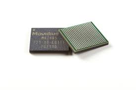
7.Intel Movidius Myriad Vision Processing Unit
Intel Movidius VPUs enables demanding computer vision and edge AI workloads with efficiency. By coupling highly parallel programmable compute with workload-specific hardware acceleration in a unique architecture that minimizes data movement, Movidius VPUs achieve a balance of power efficiency and compute performance. VPU technology enables intelligent cameras, edge servers and AI appliances with deep neural network and computer vision based applications in areas such as visual retail, security and safety, and industrial automation.
8.What is VPU technology?
A vision processing unit (VPU) is an emerging class of microprocessor; it is a specific type of AI accelerator, designed to accelerate machine vision tasks.
9.How to install D435 camera, Windows and Linux.
3.Establish communication with the Intel RealSense T265/D435 camera.
Steps.
To be able to communicate with the cameras, Intel has created a software development kit (SDK), Its name is Intel RealSense 2.0 SDK. From my Virtual Machine (Oracle VM) I have searched the web for the SDK 2.0 software and I have downloaded it into my VMachine (Linux).
https://github.com/IntelRealSense/librealsense

Once found and downloaded, we install the python libraries.
“Python Wrapper for Intel Real Sense 2.0, provides the C++ to python binding required to access the SDK”
4. Send the data received from the camera D435 to the controller
After installing everything required we tried to run the code (dronbot) but it appears that the variable pose is NULL. After researching, we came to this github post, where it is explained that stream pose is only accessible for T265 cameras, and that it is a mode not supported in 400 series cameras.
# dronbot First import the library
import pyrealsense2 as rs

# Create a context object. This object owns the handles to all connected realsense devices
pipe = rs.pipeline()

# Build config object and request pose data
cfg = rs.config()
cfg.enable_stream(rs.stream.depth, 1280, 720, rs.format.z16, 6)
# Start streaming with requested config
pipe.start(cfg)

try:
    while True:
        # Create a pipeline object. This object configures the streaming camera and owns it's handle
        frames = pipe.wait_for_frames()
        depth = frames.get_depth_frame()

        print(depth)
        pose = frames.get_pose_frame()
        print(pose)
        if pose:
            # Print some of the pose data to the terminal
            data = pose.get_pose_data()
            print("Frame #{}".format(pose.frame_number))
            print("Position: {}".format(data.translation))
            print("Velocity: {}".format(data.velocity))
            print("Acceleration: {}\n".format(data.acceleration))
            print("Rotation: {}\n".format(data.rotation))
finally:
    pipe.stop()
That is, the variables translocation, velocity, rotation, and so on. Calculations are not available on this camera.
5.Configure the controller to navigate without GPS.Adjust the Kalman filter to optimise navigation
Before starting, it is important to review to remember what is the Kalman filter and what problem can we solve with this algorithm.
What is a Kalman filter applied to a vehicle and how does it work? A Kalman filter is an algorithm used to estimate the variables of a system based on measurements with noise. What this algorithm does is calculate the different probabilities of the state of the system, subsequently superimposing them with the different measurements taking into account their added noise component. That is why the Kalman filter is perfect for using embedded systems where the sensors, to collect information from the environment, have a lot of noise.
The Kalman filter can be separated into two main steps:
The prediction where, based on the previous state of the system and the equations that govern its evolution, we are going to predict the current state.
The second part is the correction, part in which, with the measurement data from the sensors, we correct the first prediction.