At this point, we are ready to assembly all components and finally have our drone ready to fly. The following video provides a great guide for the assembly: PixHawk/Mission Planner/ArduCopter Build for Beginners: Installation – YouTube. However, we will also describe the steps in this post together with some pictures of the process.
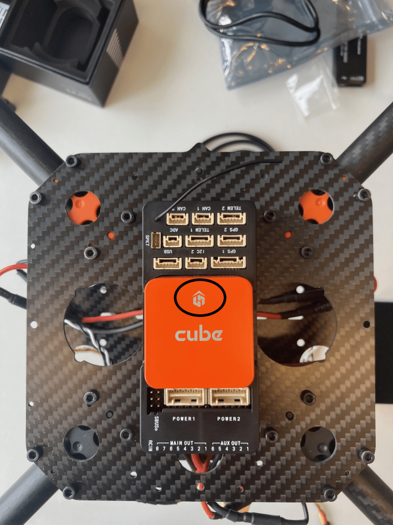
First step is to fix the autopilot into the frame. Make sure the forward of the Pixhawk is alligned to the front of the frame, which shouldn’t be a problem once you finde the arrow pointing forward. In the next image it is rounded in a black circle.
Then, try to stick it into the frame as leveld and straight as possible with the white stickers provided in the PIxhawk box.
Moving on, it’s now time to connect the autopilot and the radio receiver. This connection is made with the SBUS Out port directly to the RC IN port of the Pixhawk.
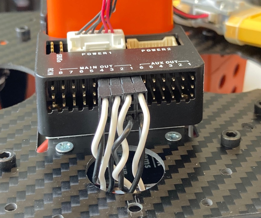
Next up, time to connect the motors to the autopilot. In this step is very important to have two things really clear:
- Which PWM cable corresponds to each motor. A smart solution given by the video is to mark the number of the motor on the end of the cable.
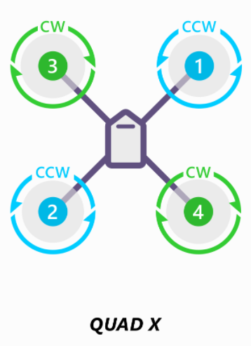
- Know the numeration of the motors in order to connect the cables to the correct port. The next image shows the distribution for our case, however, the following website will give you information on the present and different types of drones: Connect ESCs and Motors — Copter documentation (ardupilot.org)
It’s time know to mount the GPS onto the transparent plate. When doing this, make sure to install the GPS antenna on the forward part of the frame.
Now it’s turn to install the altimeter and its structure, which should also go in the forward part of the drone.
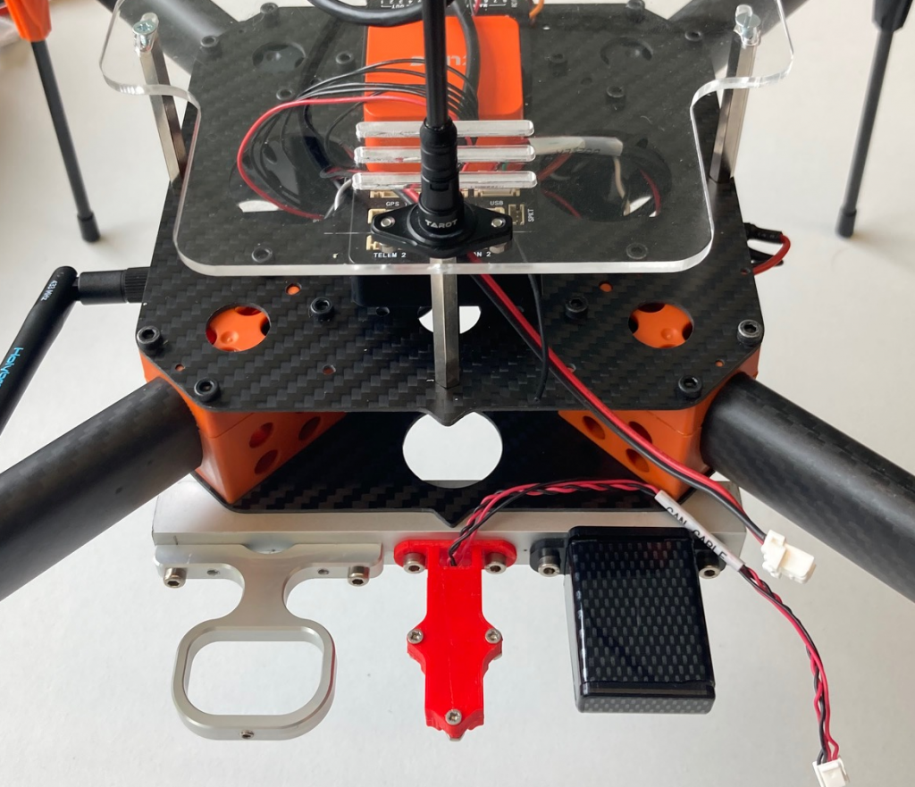
Once the structure is fixed, you can install the optical sensor, which will be connected to the I2C port of the autopilot.
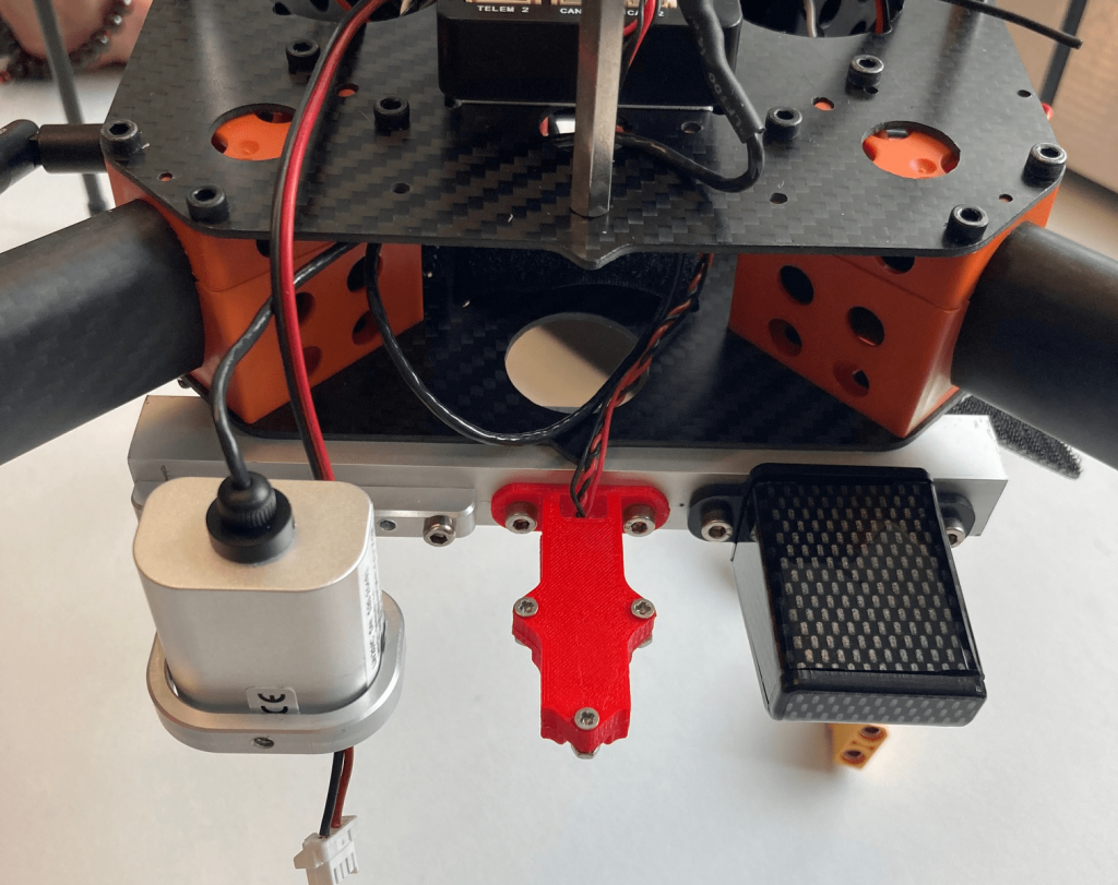
Now, we will install the telemetry radio, the component that will allow the Pixhawk and the Mission Planner software to communicate wirelessly.
Try to fit the radio in the inside of the main frame. We did it in such a way that the antenna is outside of the frame, but the rest of the radio is inside and well protected. The radio has to be connected to the Telem1 port of the autopilot.
Finally, the last two steps are installing the buzzer, which you should connect to the USB port, and fixing the straps that will hold the battery on the back of the bottom frame.
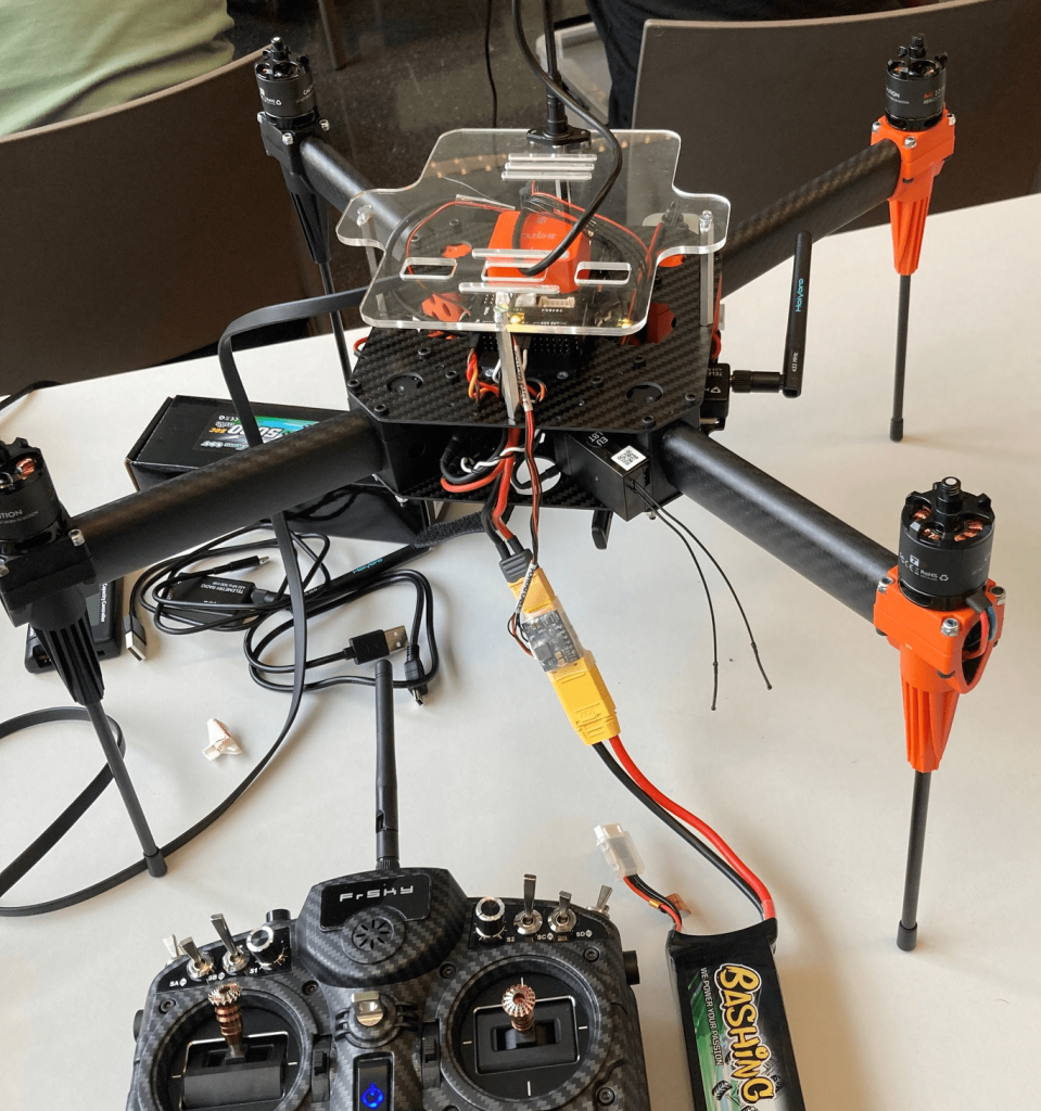
And that’s it! The only thing left now are the propellers, which we only installed just before the flight for safety reasons. The assembly of this last parts is not difficult, however you have to pay atenttion to details such as the direction to which the autopilot is facing, which cables go to which port…
Remember that you can always follow the video we provided in the beginning of the post to have a clear vision of the different steps.
0 Comments