Once we have assemblied our drone and all the components are already on the frame, we are only one step away from being able to fly it for the very first time: the calibration.
In order to calibrate our drone and some of the sensors we will be using MissionPlanner.
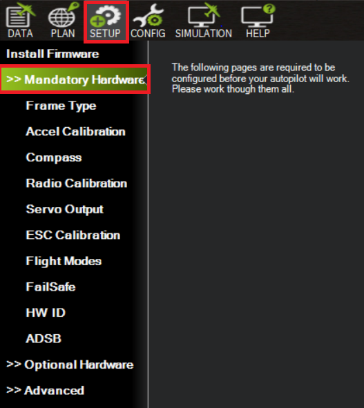
The more important features and tasks to do during the calibration process can be found in the SETUP tab >> Mandatory Hardware, as it is shown in the image below
Frame calibration
Regarding to frame calibration part, we will have to select what is the frame structure that is being used. In our case it will be a quadcopter using an X motor distribution pattern.
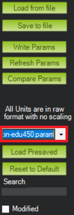
In addition, there is an extra configuration that can be set up and might help us to get a better behaviour during the flight. This option can be found in the CONFIG tab, FULL PARAMETER LIST section.
Inside this section we will find below the right top left corner a box where we are going to be able to select our frame model.
After selecting the model we are using, the Hexsoon EDU450, and we click on write parameters, this will update several parameters in our flight controller according to our frame, which will result in a better response of our drone during the flights.
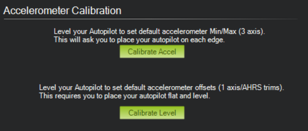
Accelerometer Calibration
This section will be straightfoward and will consist in following the set of instructions that will be given from MissionPlanner in order to get a successful accelerometer calibration.
First part will ask us to place our drone on different angles in order to detect the maximun an minimum values of the accelerometer, as it is already explained in the instructions that can be seen in the image.
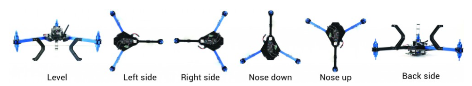
This image, extracted from an ardupilot post, will show us which are the positions that will be demanded:
Finally, to end this process all we have to do is set the drone in a flat surface, for example the ground, and click on “Calibrate Level”
Compass calibration
When we get to the compass calibration window, we will have to make sure that in the upper part of it, we select the external compass of our GPS as it is shown in the image. This is the one that has “UAVCAN” as its Bus type, since we know our GPS connection is done via CAN.
Once selected the compass, we click on “Start”. What we will have to do in this case is similar to what we did for the accelerometer calibration, but in this case we will not only have to set our drone in certain positions, we will also have to rotate around all the axis in order to fill the Mag1, Mag2 and Mag3 bars.
After filling the bars, a notification from MissionPlanner will be shown in the screen notifying if the calibration succeeded or not.
In case of consecutive fails during this process, we can relax the fitness to make it more permissive and succeed with it.
This video from an ardupilot post may be helpful to get an idea of how this process should be done:
It is recommended to repeat this calibration everytime we flight in a different location, due to meteorologic/atmosferic changes that might have a negative influence on the compass, with a negative repercussion during the flights
RC Calibration
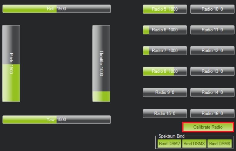
This calibration task will allow us to check how many available channels we have and which are their maximum and minimum values.
After clicking on the “Calibrate Radio” button we will have to press and move all the sticks and buttons in order to detect which are their values on the different positions.
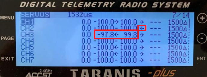
It is recommended that all the obtained values in all the channels have their minimum and maximum values in between 1000 and 2000 ms. If we are in the situation where our values are out of the limits or we want to invert one of the channels (for example the pitch), we can change it inside the RC or using OpenTX.
The image below shows the screen we have to use for this when using the RC for this purpose
Flight Modes calibration
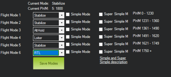
After having configured our RC following the instructions and doing the steps written in the Transversal Project Guide activity 3, now our RC is able to switch in between 6 different flight modes switching the positions of 2 sticks.
In the MissionPlanner’s tab we will be able to assign the modes we want to the 6 different positions we have. In our case we have selected the modes Stabilize and AltHold, which do not use the GPS, loiter where position calculation is assisted by the GPS an RTL to end the future missions and make the drone return the point where the mission started.
Linking the telemetry modules
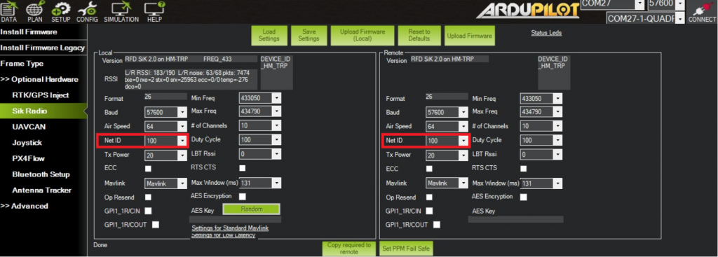
Another important step to do, specially when working in a environment with several drones, is check if the telemetry module onboard and the module used on the ground station are linked and paired. Otherwise we could stablish connection with another dron that is not ours and interfere on other’s work.
To do that we have to go this time to the Optional Hardware setup and click on “Sik Radio”. The following screen will appear:
We have to make sure that the Net ID parameter is the same in both telemetry modules and save the setting once the change is done.
ESC Calibration
This is the only calibration that we will do without the help of MissionPlanner, since there is an alternative method that allows us to do it in a more easier way:
1st step: Disconnect the battery from our drone, set the throttle stick to the maximum position in our RC and plug the battery again.
2nd step: After reconnecting the battery, we will wait for the autopilot to initialize again. When we see the GPS module lights are flashing in different colors, we unplug the battery again and plug it again after 2 or 3 seconds. This will send the maximum throttle position when autopilot reconnects again and the ESCs will enter into the calibration mode. We will hear sonorous signals when this happens.
3rd step: Once we are in the calibration mode, we set the throttle stick to the minimum position. Now if we pay attention we will hear sounds from each of the 4 motors. After hearing the alerts from all the motors, we proceed to unplug the battery for the last time, and next time we plug it again, all the ESCs will be already succesfully calibrated.
The following video shows us how to do this exact process and may help with the understanding of this calibration (minute 9:05).
Motor test
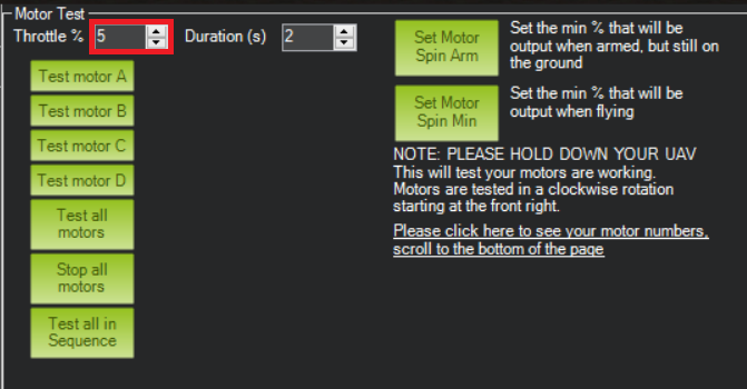
Final step we have to do is check if the motors are spinning in the right direction or not. To do this, MissionPlanner has an option in the Option Hardware tab called “Motor test”. Our screen will look like that once we are inside this option:
We have to set the throttle % we want to use for the motor spin. We recommend to start setting up low values for it and gradually increase them until the motor starts spinning.
We had a problem where our motors would not spin when we tried to test them. The solution was to increase the throttle % until they started to do so. In our case values above 19% were needed to make the motors spin.
After doing the tests, if all the motors are spinning in the right direction, fantastic, now our drone is ready to do the first flight test. In case one or more of the motors are not spinning in the right direction, we will have to invert the cable connections of the motor to the ESCs in order to change the spin rotation.
From the table shown below, you can see the short description, prices of the components, and where you can buy them. Brand name & Model Description Price Where we can buy it? 1 Pixhawk Cube Read more…
As mentioned in Activity 11, another option for controlling unmanned aircraft is dynamic flight planning. In general, in the drone platform, we use a Raspberry py as an onboard computer. The programs for our onboard Read more…
Generally, there are 3 main types of control for unmanned aircraft flights which are manual flight, static flight plan, and dynamic flight plan. The manual flight control had been done in the previous activities. Here Read more…


0 Comments