In this section we will see how to open the telemetry logs from all our flight tests and how to analyze them.
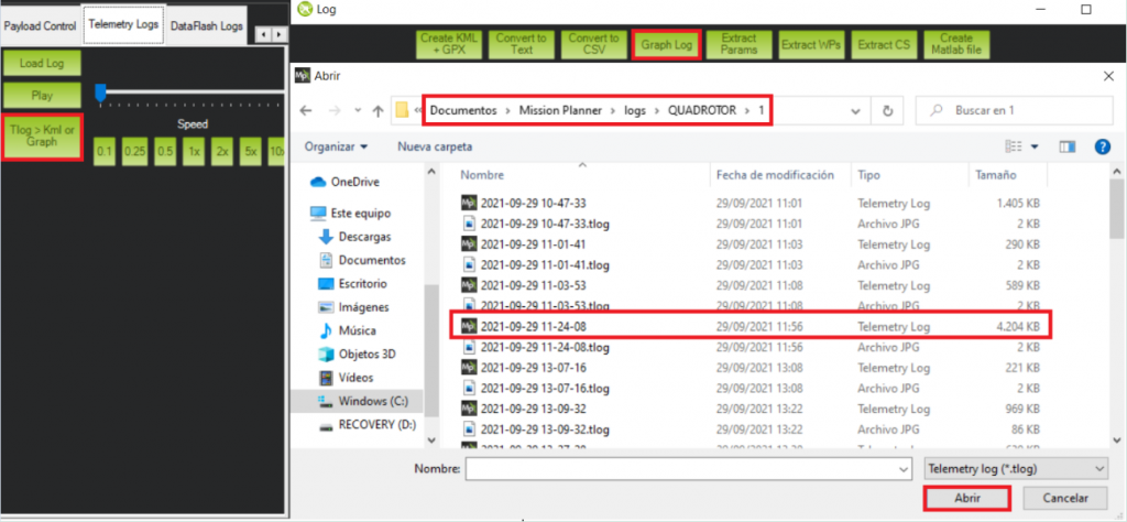
In this case we will learn how to work with the ground telemetry logs, which are stored in the computer we used as a ground station. In order to get to read these files we will need to open MissionPlanner.
Once we are in the program the next step is going to the “Telemetry Logs” tab.
Now we have to different options from this step:
1st option recreates the recorded flight in “real time”, being able to see the behaviour of the drone and its movement and position in the map.
This will allow us to monitorize again in the screen the information that we were obtaining when we were performing the flight in real time. In order to be able to visualize the parameters on this option we will have to check the box named “Tuning” located at the bottom left side, below the MissionPlanner map.
2nd option consists of plotting a complete overview of the several magnitudes and their respective variations during the flight. This option allows us to obtain with more ease the results and the process of analyzing them.
1st Method
2nd Method
Flight Telemetry Analysis
Now we will proceed to the analysis of the telemetry recorded during our flight test. In this case we will be using the 2nd method for this purpose, since its easier to present the results for this report.
As it can be seen from the image above, the log starts recording data as soon as the platform stablishes connection with the ground station. This can cause a large amount of useless data with null values that we do not want for our analysis.
By checking variations on attitude parameters or altitude, we can identify where the flight starts and focus in the flight data:
Once we have the region of interest in our log, it is a good idea in this case to graph the altitude. The main reason we are going to do this and it is going to be helpful is due to the number of flights performed during this small amount of time. We did 3 different short flights with 3 different pilots. Plotting the altitude will help us to identify the different flights very easily:
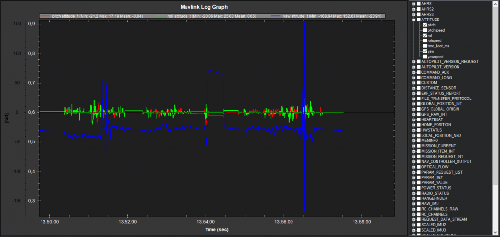
1st Flight
This first flight was done by the experience pilot.
Significant changes in the altitude can be observed in this flight as we wanted to test the drone behaviour.
The mean value of the pitch and roll is close to 0 and seems to be a stable platform as we can see at the image, barely getting variations on the blue and green lines (roll and pitch), except the moments where an input is introduced to change its position and see how is the response to said inputs.
The small variations that can be seen when there was no input or any intention to change the pitch or roll are mainly cause by the vibrations of the quadcopter.
Other factors that could be having a negative influence on that measurements could be related to the precission of the IMU.
For the yaw angle during this flight we have a variation at the end of it to test the response. The changes on this angle are fast and also it is the return to the original orientation.
2nd Flight
In this flight we have a pilot that is flying a drone for the first time ever. As it can be seen in the log the complexity of the flight is much simpler than the previous one.
The objective of the flight was to experience how was flying a drone and only use small inputs on the RC controller.
3rd Flight
This is a very similar flight to the previous one. The pilot again was a first timer flying a drone and the objective was the same.
It is a very similar flight compared with the previous one; a simple flight with constant altitude and small changes in all the angles, excluding the small exception that can be seen in the yaw angle.
The pilot almost loses the control of the drone and tried to recover ncreasing the input, causing a 360º turn in order to reset the yaw angle.
Fortunately the log shows how after this unexpected turn the drone was able to regain the stability and land safely without losing its integrity.
GPS altitude vs LiDAR altitude
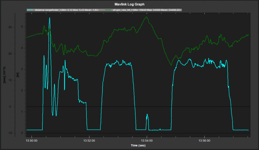
Taking advantage of using a LiDAR, we are able to compute the height in a more precise way than our “by default” drone would be able to.
In the image above we can see in blue the height calculated by the LiDAR and in green the height that was estimated by the GPS.
Can clearly see that GPS calculations are really bad and lack of precission if we compare them to the rangefinder ones. (Notice that each sensor uses a differente scale)
It would have been nice to compare the LiDAR altitude to the one generated by the IMU barometer, but as we are analyzing the ground station telemetry logs and not the flight logs, we are not able to access to that information.
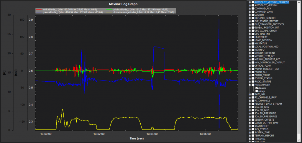
In order to get an idea of we would have obtained, the image below shows the LiDAR height vs ABS pressure. If we had the IMU altitude, the pattern we would obtain would very similar to the pressure one but inverted (lower the pressure, higher the altitude).
From that graph, we can imagine that precission obtained from the IMU altitude would be lower than the one provided by the LiDAR.
As mentioned in Activity 11, another option for controlling unmanned aircraft is dynamic flight planning. In general, in the drone platform, we use a Raspberry py as an onboard computer. The programs for our onboard Read more…
Generally, there are 3 main types of control for unmanned aircraft flights which are manual flight, static flight plan, and dynamic flight plan. The manual flight control had been done in the previous activities. Here Read more…
Once we have assemblied our drone and all the components are already on the frame, we are only one step away from being able to fly it for the very first time: the calibration. In Read more…


1 Comment
Carlos Jupón · 17 de October de 2021 at 12:00
Sheeeeeeesh