
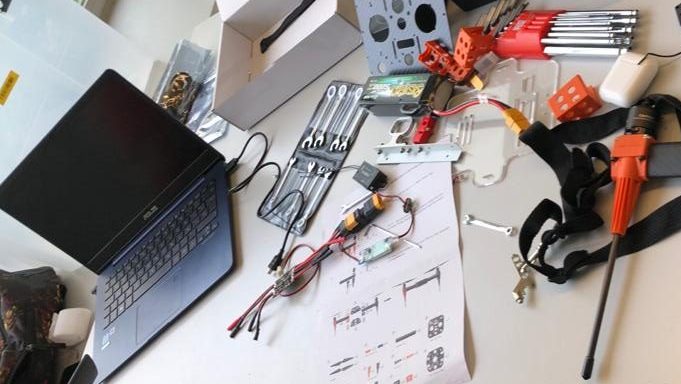
The third step of this phase 1 is based on learning how to configure it correctly to control the speed of one of the motors that we will use and the position of a servo. So, in order to do this activity, the following list of components are needed:
- Radio.
- Radio receiver. (inside element 12)
- The cable to supply power to the receiver with voltage level adapter (UBEC). (inside element 2)
- A motor and his ESC.
- A servo. (Proportioned by the teacher)
- Power distribution board. (inside element 2)
- Battery.
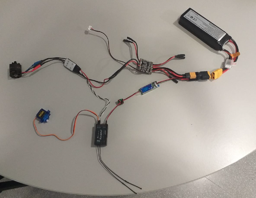
In order to control the motor and the servo, we connect the motor in channel 1 and the servo in channel 2 of the radio receiver. In the following images you can see the connections started and finished:
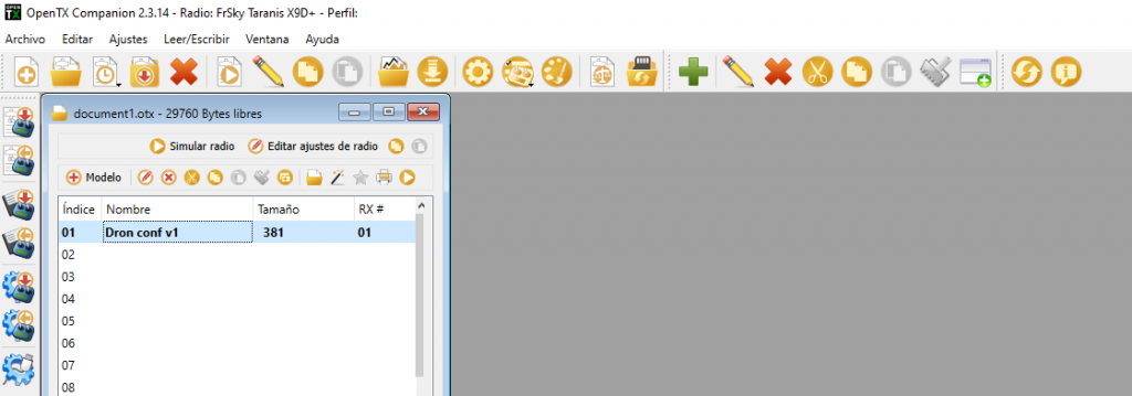
In order to do the radio configuration, we used the Open TX software. Also, the configuration can be done directly in the radio, but doing this in the software is more comfortable and easy.
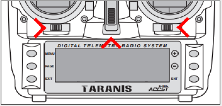
To do this, the firs step is to install the software in a computer and after that, connect the radio to the computer via USB. For the computer, in order to detect the radio, we have to put it in USB mode. This is really simple, first of all, you have to press and maintain during 3/4 seconds the three buttons shown in the next figure, and then connect the cable to the PC.
Once the radio has been detected by the software, the following step is to create a new model, we call “Dron conf v1”. This model is the file in which the different channels are configurated and sent to the radio. So, to configurate them, we have to edit the model (right click button), select the mixes window, and associate the channel 1 to the Thr (will be the motor) and channel 2 with the SB switch (will be the servo). Finally, save the model and send to the radio.
Here you have some photos about this process (the configuration shown is the finall one, with all the channels needed because we overwrote this first configuration):
If you want, there is the simulation option in order to see that every channel is well configurated, and after that, you are able to send to the radio.
Next, is time to bind the transmitter to the receiver. To do this process, the next video was followed:
After this last step, we could control the motor and the servo as we expected. In this point, it is important to know that if you want to use another model, you must do the binding process again with the new model. In our case, as we mentioned before, we overwrote the configurations in the same model, so it wasn’t necessary to do it again.
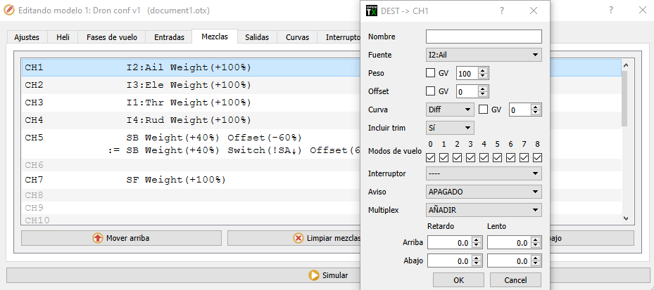
Once this worked well, we did the final configuration for the flight tests. To do this it was needed to put the necessary chanells associated to each switch and joysticks:
- Channel 1 associated to Ail.
- Channel 2 associated to Ele.
- Channel 3 associated to Thr.
- Channel 4 associated to Rud.
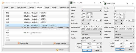
- In Channel 5 a mix must be configured to be able to select between 4 different flight modes, using the SA and SB switches.
This last point is really important in order to change the flight mode during the flight quickly. Each switch has 3 positions, so with this mix configuration is able to control 9 different flight modes. In the next figure this configuration is shown:
To finish this activity, we advance that the Channel 7 is associated to the SF switch, in order to arm and disarm the Drone with only one switch. It will be seen in Activity #7.