In activity # 8 of phase 1, we flew the flight manually, with the help of the Mission Planner ground station, but we were the ones who sent the commands to the Drone from the radio controller. In this activity, we will learn how to create flight plans and send them to our Drone controller in order to perform an automatic flight.
Before starting with the activity, it is necessary to mention something very important and is that due to the restrictions to be able to fly the Drone in the area where this project is being developed, this activity has been done with the flight simulator that incorporates the Mission Planner itself. However, the methodology is the same, the only difference is that instead of connecting our real Drone via radio, the Drone is simulated and connected to the Mission planner using the Software In The Loop, but the steps to create flight plans and how to execute them are exactly the same.
So below we will explain the different steps to follow in order to simulate an automatic flight using the Mission Planner simulator.
The first step is to create the flight plan, to do this you need to go to the PLAN menu. In our case, we have created 2 flight plans in order to see the different options that can be chosen and in order to analyze the data obtained and ensure that the behavior of the Drone has been the same as that selected when these flight plans have been created.
The first flight plan is to see how the altitudes of the Drone can be changed automatically during the flight. The second flight plan is to see, apart from how altitudes change, how you can vary the speed in certain sections of the flight plan and we will see how to order the Drone to stop for a while (Loiter).
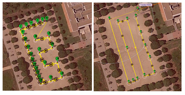
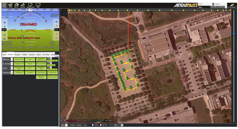
In the following photos you can see the maps with the Way Points of the route for each flight plan:
In order to create these patterns, simply click on the map and a WP will appear. These WPs will appear in a table below the map where we can change different parameters in order to customize the behavior we want in our flight. The following images show these tables:
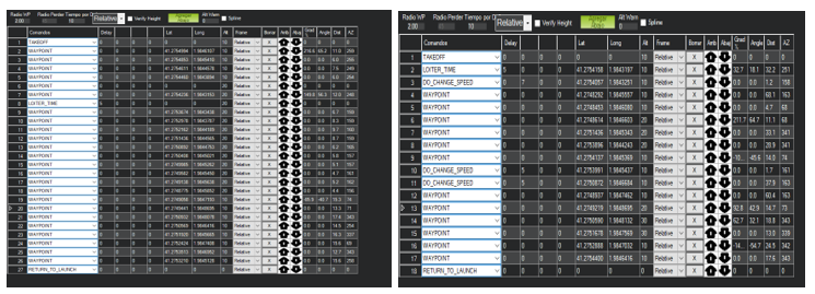
The first WP always will be the TAKEOFF, so you can select this option in the cell “Commands” and select the desired altitud for this action in the “Alt” cell. This cell is the one where you can change the altitude during the flight. So in each Waypoint we created in the first flight plan, different altitudes where selected in order to see these variations in altitude. It can be seen that from WP 6 to WP18 the altitude is changed from 10 meters to 20. Also, in this flight plan, in the WP number 8, in the “Commands” cell, we selected another WP called LOITER_TIME, and the cell next to it, a number 5 is selected. This option is used in order to tell the Drone to wait 5 seconds in this position, and after that, continue with the flight plan. After the WP 18, the altitude is changed to 10 again and the final WP is selected the RETURN_TO_LAUNCH, where the Drone goes to the HOME position decreasing its altitude.
In the right flight plan, that is the second one, we used the options mentioned in the previouse, we changed the altitude in some sections of the plan, but also here we selected in WP 3, 5 and 10 the option DO_CHANGE_SPEED. This option is used when you want to increase or decrease the speed of the Drone selecting a specific value of speed in the cell 2 next to the “Commands” of that WP. In our case, we increased the velocity up to 7 m/s. The Default velocity for this simulation is 2 m/s, so we increased 5 m/s in this WP. We will analyse all this behaviours in the final logs.
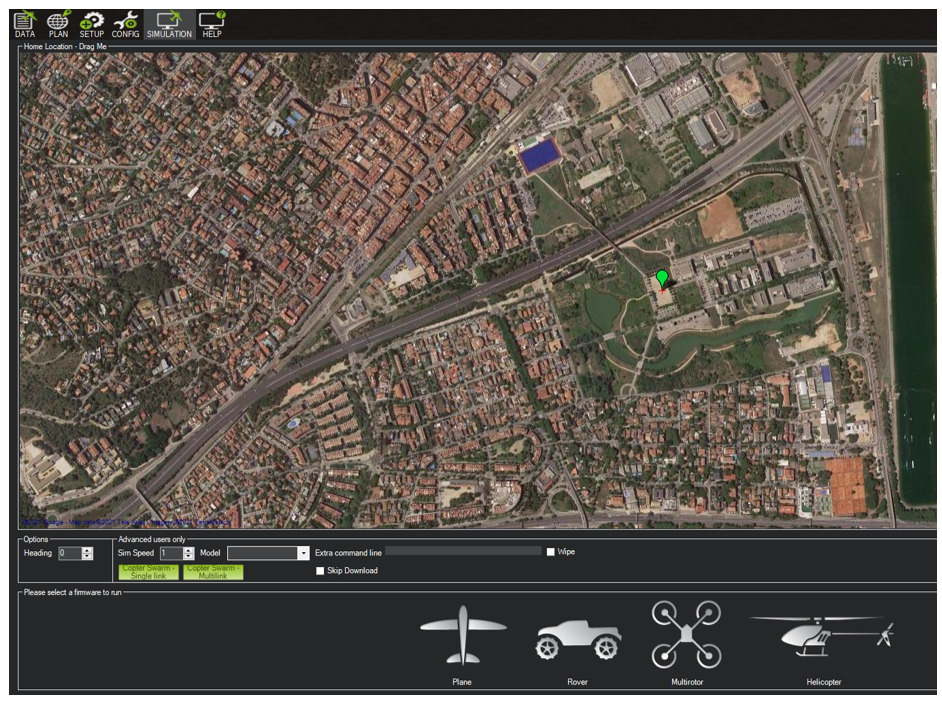
Now, it is time to save the flight plans and press the button WRITE, but first, you must connect the simulator. This is the only step different that if we do this activity with the real Drone. To do this, go to the SIMULATION menu and select the platform you want to simulate, in our case the multirotor.
When the Drone is connected, just go to the PLAN menu, press the WRITE WPs button, and then, go to the DATA menu and you will see the flight plan ready to go:
The next step now is just arms the motors and select the DO MISSION button in the left menu. After this the flight will start automatically. In the next pictures, it can be seen how the flight is being developed and also, the logs can be seen simultaneously:
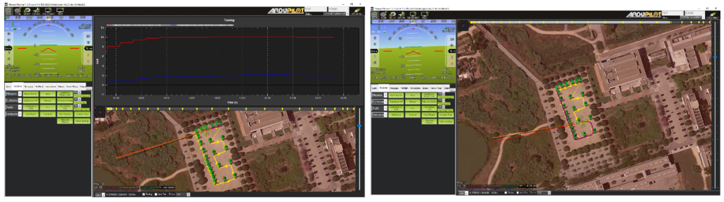
The Mission 2 (flight plan 2) is the same, just changing the pattern and some options.
Once the missions ends, the motors are disarmed automatically and the flight will stop. The next step is to disconnect the Drone, just selecting this option in the top-right button in order to save the telemetry logs for a futures analysis.
We will now look at some parameters in the logs of the extracted logs for each of the flight plans.
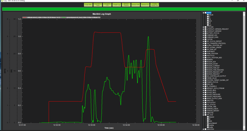
MISSION 1
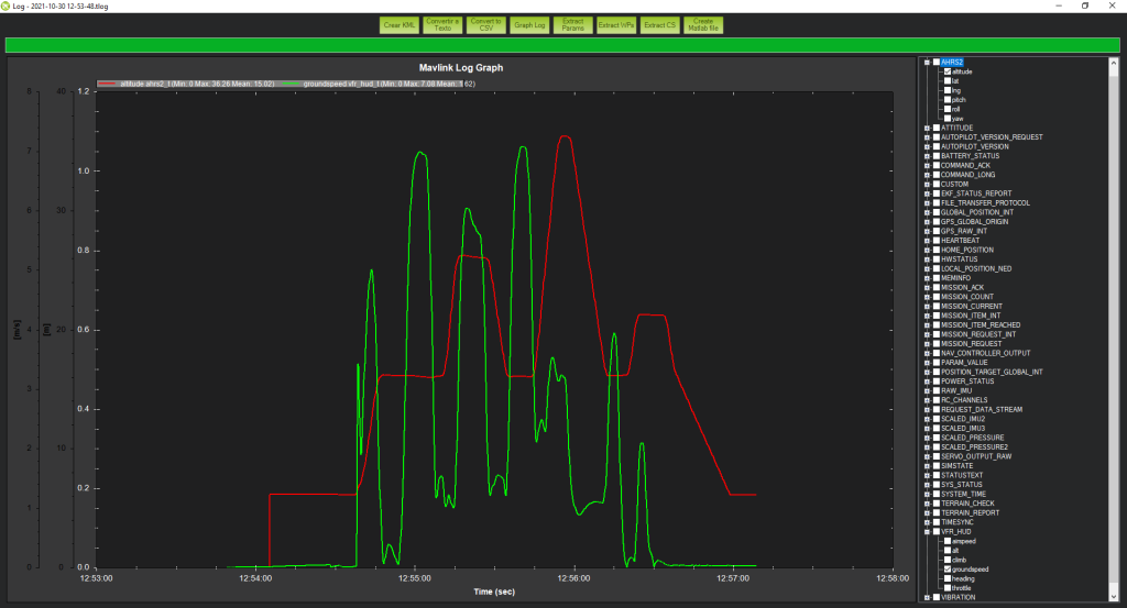
In this first graph we can see the lines of the altitude and speed of the Dron. As we said, in this first mission we wanted to check if the altitude changes were effected correctly, and as we can see in the red line there are altitude changes more or less between the 10 while and the 20, values that we had selected. If we look at the speed line, greed one, we can see that there is a moment during the flight that marks 0, this is due to the LOITER_TIME of 5 seconds. Also, some moments the ground speed is 0, this is because if the Drone is doing a hard turn, the speed is decreased a lot in order to follow as much as possible the correct way. So we can see that the behavior of the Drone has been as expected at all times.
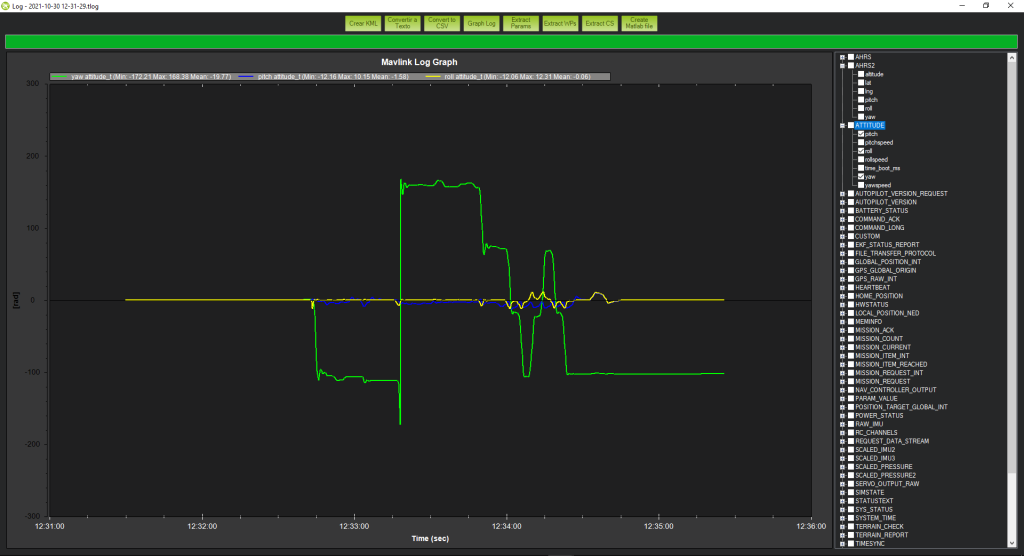
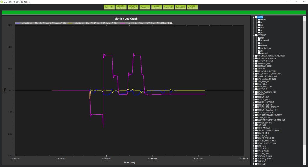
Also in the following image we can see other parameters of Pitch, Roll and Yaw, where the Yaw takes higher values due to the turns we have created in the flight plan.
MISSION 2
In this second mission, apart from changes in altitude, it is important to see how speed values can be changed. As it can be seen in the green line, the ground speed, the values reach up to 7 m/s, as they had been configured in the flight plan. There is also a time when for a period of time the speed is 0, this is due to a LOITER_TIME of 5 seconds. As for altitude, it also varies up to 30 while, as it had been set up. So we can also say that the behavior has been as expected.
Also, we can check if the values of the Roll, Pitch and Yaw.
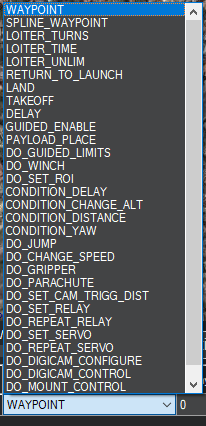
In conclusion, there are different parameters that we can configure in the flight plan in order to give different commands to the Drone according to our needs, below are all that Mission Planner allows you.
In the presented missions, the most frequent ones have been used, but others can be used such as DO_SET_SERVO or DO_PARACHUTE, in order to activate a servomotor or the emergency parachute.